AtariBits
  • Home
  • Systems
    • 576NUC+ >
      • NUCplus4
    • 1088XEL >
      • XEL-CF Drive
      • XEL-CF3 Rapidus Variant
      • Accessories
      • XEL Archives
    • 1088XLD >
      • RGB2VGA-XLD
      • ARROW2JOY-XLD
    • CV-NUC+
  • TransKey
    • TK-II >
      • TK-II Manual
      • Installation
      • Device Compatibility
      • TK-II Archives
    • TK-II-STEREO
    • TK-II Control
  • XEP80-II
  • JOY2PIC
  • MOUSE
  • MIDI
    • MIDI 3D Printed Cases
  • UGV
    • Old UGV Archive
  • SDrive
  • RAM
  • Blog

C64 Goodies (continued... part 5)

2/29/2024

 
Picture
The PCBs for the C64-VGATE project are entering the final phase of design and are looking very good indeed.

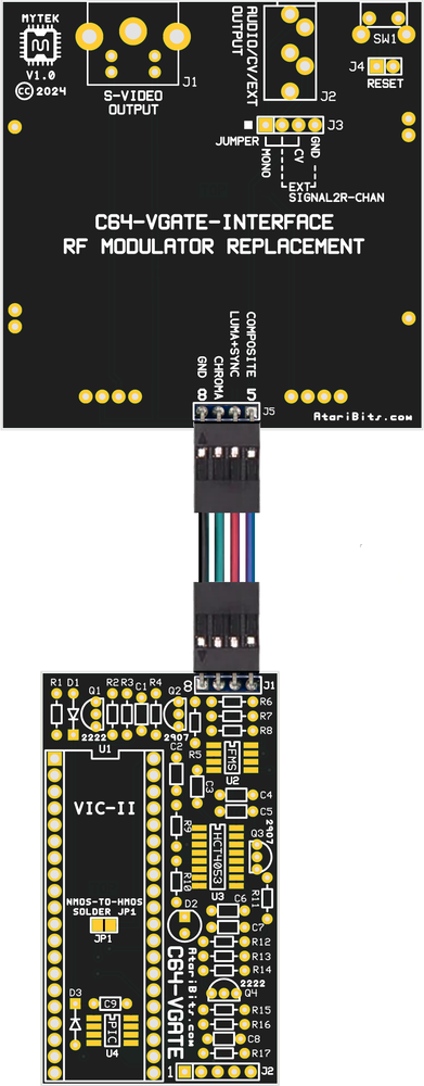
The top board as the silkscreen describes is meant to replace the stock RF Modulator utilizing a few of the existing mounting holes to line up the board with its S-Video and Audio jacks to the holes in the rear of the case. This is then interconnected with the C64-VGATE Main board via a short dual female Dupont Cable (I tried to make this a straight shot to keep the cable flat and untwisted).

The 3.5mm Stereo jack outputs the stock SID audio to the left channel, with provision to route either a 2nd SID audio to the right channel, or gives the option of having Composite or perhaps LumaCode video on this output instead. I got the idea to do this multi purpose assignment by watching a similar project on TheRetroChannel.

The C64-VGATE Main board contains the meat of this project, containing all of the actual electronics that perform the signal amplification, conditioning, and over-scan elimination of the video from the VIC-II chip which it piggybacks. The RF Replacement board is passive, containing only headers and jacks.

There is also provision for installing a later HMOS version of the VIC-II chip in the older NMOS boards, thus eliminating the necessity of an adapter board.

And finally if one is inclined to do so, a small hole can be drilled in the back of the case next to where the 3.5mm jack resides for an optional hard reset switch. I also glommed onto this idea from The RetroChannel's project, and although it got eliminated on their 2nd revision board, I decided it was a good idea to incorporate this idea into my board for that just in case scenario.

Schematics

c64-vgate_v1.0_schema_revised.pdf
File Size: 494 kb
File Type: pdf
Download File

Changes: R1 individual values for NMOS or HMOS VIC-II variants,
Added R11 pull-down resistor for Q3 collector,
Added RF Modulator Replacement Interface PCB for Short Board


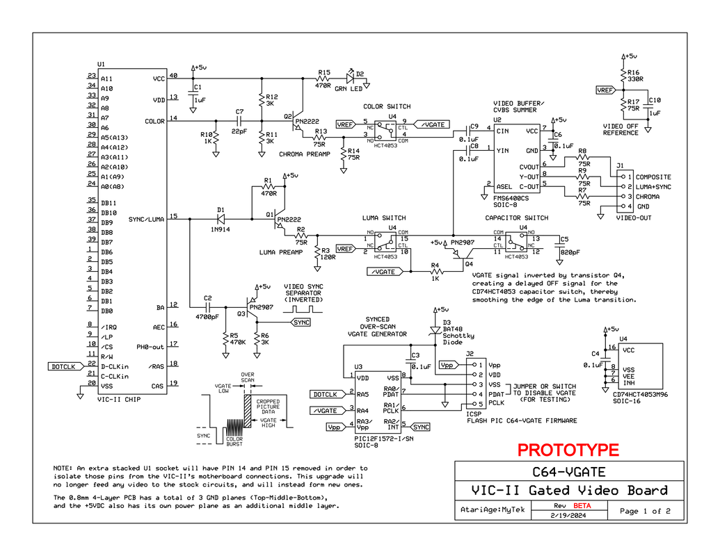
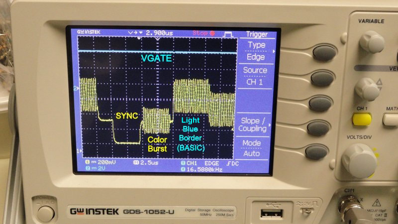
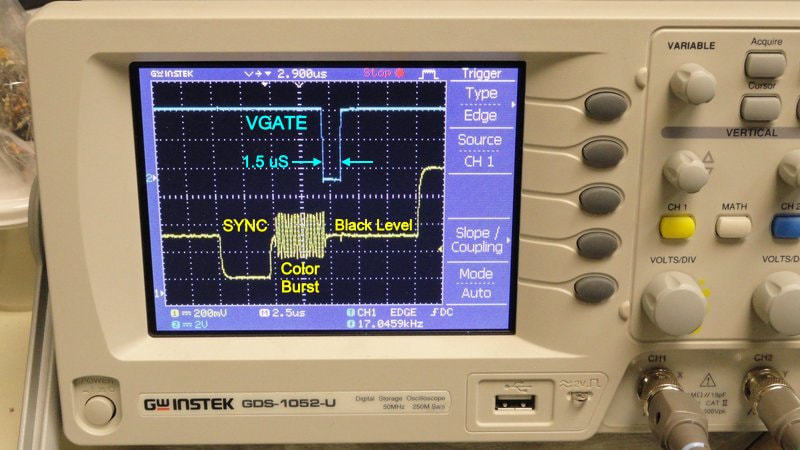
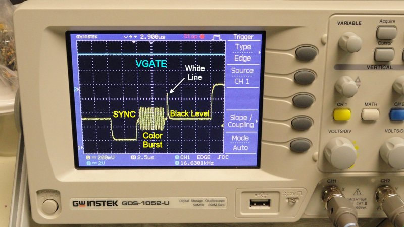
 Notes: On March 3rd it was discovered that changing from an NMOS VIC-II over to an HMOS version required an increased resistance for R1 in the collector-to-base feedback for Q1 (Luma Preamp). This allows matching the black level voltage for a proper VGATE "no video" bias, which differs between NMOS and HMOS variants. The two different possible R1 resistor values are now shown in the latest schematic download attached to this blog post.

On March 4th erratic operation was observed in the smoothing capacitor circuit caused by PNP transistor Q3's collector being in a floating state when not turned ON, thus requiring a pull-down resistor for its OFF state. The pull-down resistor reused the component ID "R11" due to its location on the board, and all others that followed had their IDs incremented by one. This can't be seen in the board image above, but was reflected in the schematics.

Also after receiving an eBay Canada C64C which had the short motherboard (PCB ASSY: 250469), I was able to take measurements and create a new short board version of the RF Replacement Interface PCB, and then add it to the documentation, as well as generate gerber files for future release.


After I do some more checks of the layout, gerbers will be sent off to JLCPCB to get a few samples manufactured for testing.

- Michael

Previous Post (Next Post)

C64 Goodies (continued... part 4)

2/22/2024

 
I noticed that everyone working on cleaning up the video in the C64 likes to use the Easy Flash 3 menu as a reference image. So in keeping with this spirit I extracted the ef3-menu-1.2.0.crt contained in the zip file I downloaded from HERE and copied it too my Kung Fu Flash Cart's SD card, and then proceeded to spend the next 2 hours trying to take a picture of it from my VIZO LCD monitor. Why 2 hours you may ask? Well it all came down to trying to avoid the moiré pattern that the camera insisted was there, but really wasn't in reality.

Finally I achieved success and got a very clean image of what my eyes were actually seeing. And believe me it was every bit as good as the image below.
Picture
Real Image Produced by my C64-VGATE Prototype Video Board via the S-Video Connection
This looks so good, that I doubt it would have been noticibly better with one of the C64 HDMI solutions, other than perhaps a bit more crispness.

So not only has my alternative video board gotten rid of the over scan and resultant white line, it also produces rather excellent video quality as well. And because of the FMS6400CS video buffer/summer chip, it will also render some of the best composite video ever seen coming out of this system, without compromising the S-Video, or requiring a switch to disable it. In fact both video outputs can be used simultaneously without any issues or interference.

Edit: you may have noticed that there are some horizontal bands that appear darker. Yes that was really there and not an artifact created by the camera. As it turns out my last revision to the schematic where I had changed two resistor values to achieve a higher Luma output, was a mistake. After I changed them back that dark banding completely disappeared. Some times it's best to leave well enough alone.

The banding was in areas that had a particularly bright object being displayed, thus exceeding the nominal 1 Volt peak-to-peak video level, and causing this unwanted side effect due to the overdrive.

I'll be re-posting the schematic with the changes after I add the interface board schematic as the 2nd page.

- Michael

Previous Post (Next Post)

C64 Goodies (continued... part 3)

2/19/2024

 
Well I started thinking more about this C64-VGATE board today, and specifically about the look of the video wave form as compared to what's considered the standard in the industry. And I noticed that what is called the Breezeway, is non existent out of the VIC-II video chip (reference image below for what it should look like).
Picture
Standard NTSC Waveform and it's Attributes
In the NTSC standard, there is a 0.6 uS long blanking level just after the end of SYNC and prior to where the color burst is suppose to begin called the Breezeway. As I stated earlier this is virtually non-existent where the VIC-II is concerned, with it's color burst immediately following the end of the SYNC pulse. And another not as significant change is that the VIC-II outputs a rather long color burst, which in itself is not usually going to be a problem, but for the sake of making it a bit more standard it should be shortened (some video converters might take issue with it's longer state).

Luckily no hardware change is required to implement these changes, and everything can be adjusted within the PIC chip's firmware. Specifically in the Interrupt section of the assembly code as seen below...

    org     0x004          ; Processor interrupt vector


    movlw   0AH           ; Wait 4.7 uS (sync)
    call    dly_405ns


    bcf     VGATE          ; Turn off video for 0.6 uS (add breezeway)
    nop
    nop
    nop
    nop


    bsf     VGATE          ; Turn on video for 3 uS (color burst)
    movlw   06H
    call    dly_405ns
   

    bcf     VGATE          ; Turn off video for 2.4 uS (over-scan deleted)
    movlw   05H           ; Also shorten tail end of color burst
    call    dly_405ns

   
    bsf     VGATE          ; Turn on video (display active video data)


    banksel INTCON          ; Clear interrupt flag
    bcf     INTCON,INTF
    retfie                  ; Leave interrupt

In this new firmware version the Color Burst was shortened to 3 uS which is the equivalent of 10 cycles, with the standard being as little as 9 or as much as 11 cycles. The 0.6 uS Breezeway got re-instated. And in order to eliminate any left side over scan and to shorten the Color Burst , the Back Porch was lengthened by 2.6 uS, and set to begin before the VIC-II's color burst ended. This last part is about 1 uS longer than the standard, but isn't a detriment.

By the way where retro computer video is concerned, there is no separate blanking vs. black level, they are one in the same.

Here's how things compare with stock video shown on the left and VGATE enabled video on the right (Color Burst is in the middle)...

Picture
Stock VIC-II Video - No VGATE
Picture
VGATE turned ON
On the stock video output you can see that the Breezeway is extremely short and practically merged with the Color Burst which looks to be 15 cycles long. Whereas with VGATE engaged, and using the new firmware, we now have a bit more normal looking video with a standard 0.6 uS Breezeway and a 10 cycle Color Burst.

The firmware is now at rev 1.1 and available for download below.

c64-vgate_1.1.asm
File Size: 4 kb
File Type: asm
Download File

c64-vgate_1.1.hex
File Size: 0 kb
File Type: hex
Download File


I presently don't have the means to test this in a PAL machine, but if it's anything like the Atari VGATE version I think it will automatically scale to the slower speed (60 vs. 50Hz). If not then a PAL specific firmware version will need to be developed by adjusting the timing in the interrupt routine.

- Michael

Previous Post (Next Post)

C64 Goodies (continued... part 2)

2/18/2024

 
I got the sample boards from JLCPCB for what I had called C64-JBgone, and after testing, it did clean up the video, but the jail bars although lighter could still be seen against darker backgrounds. So I accept that this must be coming from inside the VIC-II chip, and because of this there really is no way to completely eliminate this effect. I believe Adrian Black from Adrian's Digital Basement came to a similar conclusion after much experimentation of his own.

And I also played around with some of the ideas embodied within the LumaFix64 mod, but found that approach to be lacking in overall effectiveness, and in certain situations making things even worse.

I'm pretty content with the progress I made via improved video  circuit design and better shielding. However the over scan and white line problem visible on the left was in need of a solution, so a new plan was formulated, and that plan is the C64-VGATE VIC-II Video Board.
Picture
Click Image to Enlarge
I took what I had learned in the previous design, which had a lot in common with the first version C64 motherboard video output circuit, and then streamlined it before adding what I call VGATE technology. Which in a nutshell blanks out a specified amount of over scan (what was never meant to be seen) either from the left or right side of the screen, or in some cases like on the Atari - both sides. So for the C64, over scan only occurred on the left side of the screen with a thin white line visible on the extreme left when viewed on an LCD wide screen monitor. The white line was something new to me, but would be cured by the over scan blanking I was implementing.

The Video Gating (VGATE) where the blanking occurs, is controlled by a PIC microcontroller that derives its clock from the VIC-II Dot Clock on pin-22 (multiplied by 4 inside the PIC with a PLL), and then gets synced at the beginning of every line by the video's CSYNC signal. This gives us very precise control of where and when the gating signal gets turned on or off, and where it flips the analog switches to an OFF state in order to stop the video from displaying. The code for the PIC's firmware needed to be fast, so the source was written in assembly language and then GPASM was used to compile the Microchip PIC machine code, creating the hex file for flashing the chip. The asm text file was written and saved on a Linux box, so there may be issues with the end of line in Windows, although it should be viewable in most browsers.

c64-vgate.asm
File Size: 4 kb
File Type: asm
Download File

c64-vgate.hex
File Size: 0 kb
File Type: hex
Download File


Prior to the video switches, there are two preamps for the Luma and the Chroma which condition the signals coming from the VIC-II to an acceptable level, and match up the black level between them. Following the video switches we feed a special video buffer/summing IC chip (FMS6400CS) where the signals get boosted in current capability for a standard 75 ohm load while rendering 1V peak-to-peak video output, and also doing DC signal restoration with some filtering. And finally the Luma and Chroma also get combined inside the FMS6400CS to create an independent fully buffered composite output that will not interfere or cross-talk with the Luma/Chroma outputs.


O-Scope and HD Monitor Images
Picture
BASIC Start-Up Screen with VGATE ON (cropping left border over scan)
Picture
Picture
BASIC Start-Up Screen with VGATE OFF (full left border - no cropping)
Picture
Picture
Diagnostic Screen VGATE ON (no white line)
Picture
Picture
Diagnostic Screen VGATE OFF (white line visible)
Picture
Next will be PCB layout for the C64-VGATE board - so stay tuned!

- Michael

Previous
Post (Next Post)

    Author

    My name is Michael St. Pierre and in the early 90's I decided to create my very first Atari 8-Bit upgrade. It was called TransKey.
    ---Then soon after Atari folded and I left the scene ---
    25 years later I came back with a mission to improve upon what I had started so long ago.

    Archives

    May 2025
    March 2025
    January 2025
    December 2024
    September 2024
    August 2024
    July 2024
    May 2024
    April 2024
    February 2024
    January 2024
    December 2023
    November 2023
    August 2023
    June 2023
    May 2023
    March 2023
    January 2023
    December 2022
    August 2022
    May 2022
    April 2022
    December 2021
    October 2021
    July 2021
    June 2021
    May 2021
    April 2021
    March 2021
    February 2021
    January 2021

    Categories

    All
    576NUC+
    AtariBits News
    C64
    ColecoVision
    Industrial Applications
    Intro
    MIDI
    Monster 600XL
    Multi-Carts
    Multi-SLOT 1200XL
    NUCplus4 Assembly
    Transkey
    XEP80-II

    RSS Feed

Powered by Create your own unique website with customizable templates.