|
ARROW2JOY-XLD Keyboard Joystick Emulation for the 1088XLD
Sometimes it can be annoying having to look for a joystick in order to play your favorite game, and or switching between the keyboard and the joystick when the game requires keyboard input from the player. So I knew there were some emulators that let you use the arrow keys to mimic a joystick, and I thought wouldn't that be cool to be able to do that on my 1088XLD. Well that thought soon turned into reality, once I figured out where I would get the extra I/O lines from the PIC16F1847 chip running the TK-II firmware on my XLD. If you look at the diagram to the right, you'll see that the extra I/O came from the pins once connected to Pokey's key scan counter bits K1-K4. This was made possible by recreating a shadow counter within the PIC chip, and just using key scan counter bit-0 as the clock for that counter, and bit-5 as the sync. This was a trick taken from the AKI (Atari Keyboard Interface). Three of those re-purposed I/O pins then became an address for a 1 of 8 decoder based on the 74LS156, and the 4th acted independently as the trigger button. |
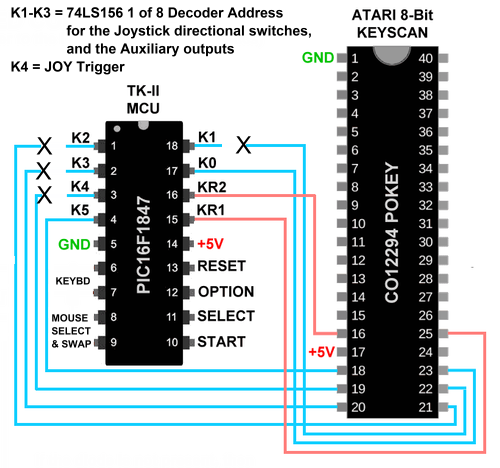
Finding the Logic to Control the Joystick Port
|
|
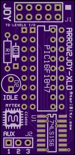
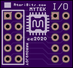
A small PCB was then created to piggyback with the 1088XLD's TK-II keyboard chip, and give us this new functionality. To access and enable the new joystick connections, the TK-II firmware required modification, with ALT+J acting as a toggle to enable or disable keyboard control of the joystick functions. When enabled, the arrow keys of the PS/2 keyboard control joystick direction, and the Left-Windows key or the Enter key on the Numerical Keypad becomes the trigger button. Additional outputs AUX 1-3 will respond to key press ALT+1-3 respectively, going low for the duration of the key press. These are active all the time, not requiring that the ALT+J joystick command be issued first. Possible uses of these outputs are left up to the user. Keep in mind that they are momentary open collector outputs, and might require a latch for use in certain applications. When no action is required, the decoder is held with it's highest bit output being selected. This will activate the yellow LED showing that the decoder is essentially idling (in standby) and waiting for a command. An interface PCB was also created to make it easier to parallel connect to the existing joystick direction and trigger bits, which are available from the top of header P1 on the Level1 I/O board, only requiring a ribbon cable for interconnection. |
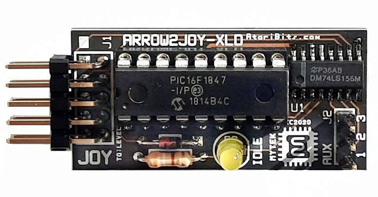
Assembled Main Board Top View
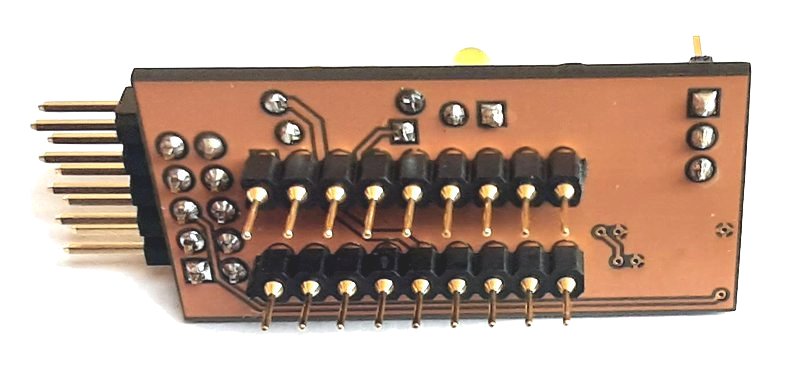
Assembled Main Board Bottom View
|

ARROW2JOY-XLD Board Set Shown Installed in 1088XLD
ARROW2JOY-XLD MAIN PCB Fabrication Files
ARROW2JOY-XLD I/O INTERFACE PCB Fabrication Files
Bill of Materials (Linked to Digi-Key P/N Unless Shown Otherwise)
ITEM 5 is a break-away style header which is to be broken down into 9-pin versions for use in this upgrade board. You should get 10 pieces x 40 pins from the eBay link, enough for 20 Arrow2Joy boards. |
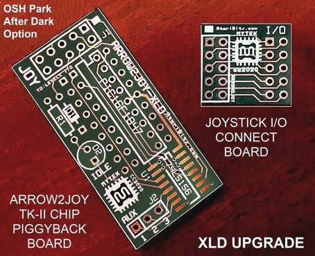 If You Don't Like Purple, there's Always Black with a Clear Solder Mask If You Don't Like Purple, there's Always Black with a Clear Solder Mask
Gerbers have been provided to allow ordering boards from where ever you want. For my needs, I've found that JLCPCB produces high quality PCBs, with fast turn-arounds, and great pricing on quantities as few as 5 pieces. ARROW2JOY-XLD Firmware Download
File Includes:
| ||||||||||||||