|
TK-II-STEREO Fully Integrated PS/2 Keyboard and Stereo Sound Board
Combining some of the most popular Pokey related upgrades for the Atari 8-Bit computer system into a single compact main board, with two choices of satellite connector interface boards. It Piggy-Backs the existing Pokey chip providing an extra socket for a 2nd Pokey chip to be added thus creating the right channel sound output (4 extra voices), and integrates the Transkey-II PS/2 keyboard adapter to allow virtually any PS/2 keyboard or numeric keypad to be utilized in tandem with the stock Atari keyboard (supports two simultaneous PS/2 devices). And for all of the Ultimate 1Meg owners, you'll be glad to know that the stereo/mono U1MB electronic switching has already been built-in, ready to be controlled without any additional hardware required. |
|
|
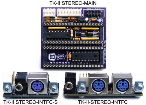
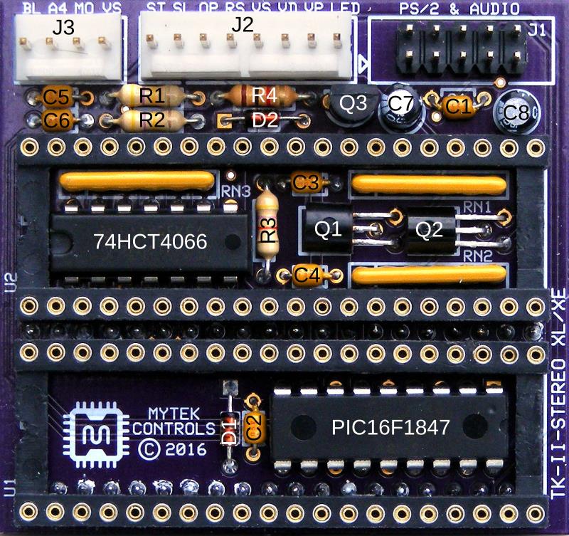
TK-II-STEREO MAIN BOARD
| ||||||||
For more information on the TK-II-STEREO and connector interface boards --- including their development history and detailed installation photos go to the AtariAge Forum TK-II-STEREO Topic. |
|
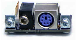
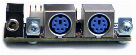
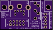
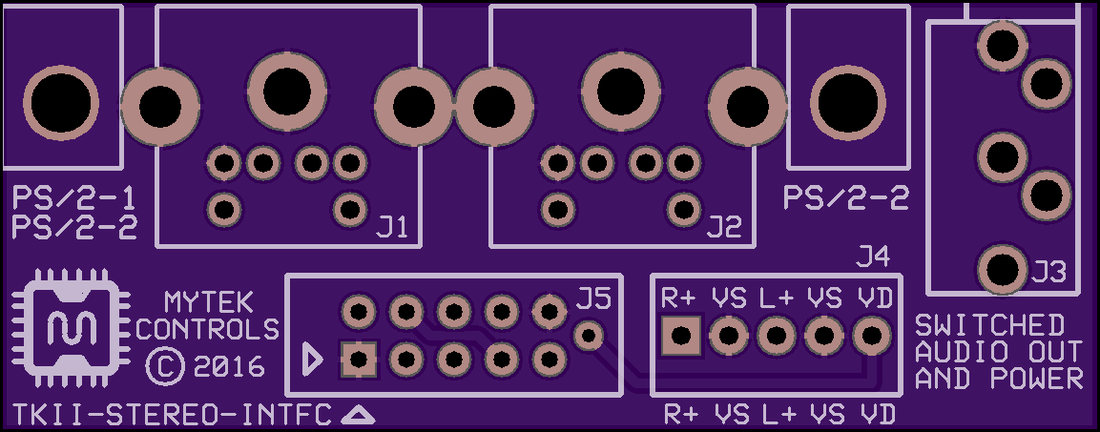
TK-II-STEREO INTERFACE
| ||||
Audio Output Specifications and Modding
The line level output from both sound channels was designed to meet the consumer audio -10 dBV standard (0.316 V RMS / 0.447 V Peak). It is a high impedance output not suitable for directly driving speaker loads, thereby requiring external amplification.
This standard was chosen because quite frankly the levels produced across the Atari 8-Bit series computers was inconsistent, ranging from quite low to very high and wasn't always a good match for present day consumer audio equipment (amplified speakers, Hi-Fi gear, LCD monitors). Also it was later discovered that a small mod done in two different ways could allow for headphones to be used. Modification For Headphone Output on already assembled PCB requires 2 each SMD 390 ohm (Mouser PN: 754-RR1220P-391D). Reference image to the top-right. I think an even better way to go if you are just starting to assemble the PCB was presented by AtariAge member marauder666 in the form of replacing the RN1 and RN2 SIP resistors with individual 1/8 watt resistors.
4 x 100K 1/8 watt (CF18JT100K) and 2 x 390 ohm 1/8 watt (CF18JT390R) This also solves the problem of finding the sometimes hard to get 100K SIP resistor networks. And it better matches the input requirements of PC sound cards causing less distortion, while providing enough drive for headphones.
|
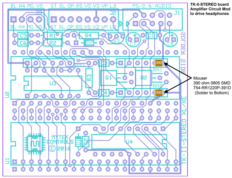
Modification to Already Assembled PCB - Click on Image to Enlarge
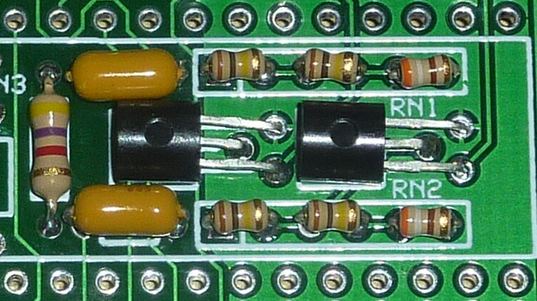
Alternative for RN1 and RN2 - Click on Image to Enlarge
|
|
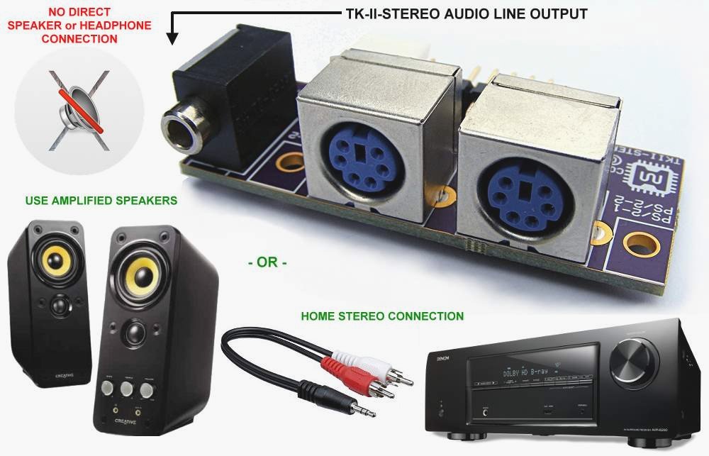
Stereo Audio Connection
The TK-II-STEREO interface board's 3.5 mm stereo line output jack, although the same as used on many of the consumer headphones in use now days, can not directly drive this type of load (for an exception: check out the resistor mod described earlier). So some sort of amplification is required.
The audio input on many computer LCD monitors already makes use of the 3.5 mm stereo connector, but sometimes in the cheaper variety this is simply wired direct to internal speakers. So it is important to determine if the monitor's speakers are indeed amplified. |
