This begins my first posting on an industrial based application for my home brew 576NUC+ Atari computer system. A very unique "Real World" application for this equally unique Atari 8-bit computer.
Background
Sometime between 2005-2006 I was approached by a company doing service work on industrial cryogenic chillers used for what was called water vapor cryopumping of vacuum chambers. These chillers acted like a selective pump for water vapor inside the chamber, by freezing it to a cryocoil, and thus trapping it in place (it would no longer be floating around inside the chamber). These vacuum chambers would be used for an assortment of applications, including environmental simulation, semiconductor fabrication of IC Chips, decorative coatings, and various other coating applications.
When servicing these units, it required having the means to subject them to a specific heat load in order to match a given customer's application. Anywhere from 90 watts up to 3600 watts of applied heat was necessary (imagine a very big electric space heater). So they wanted me to design and build them a heat load controller that they could use for testing these cryo-chillers under a simulated condition. Below you can see a diagram depicting one of those early load controllers in a typical testing set-up.
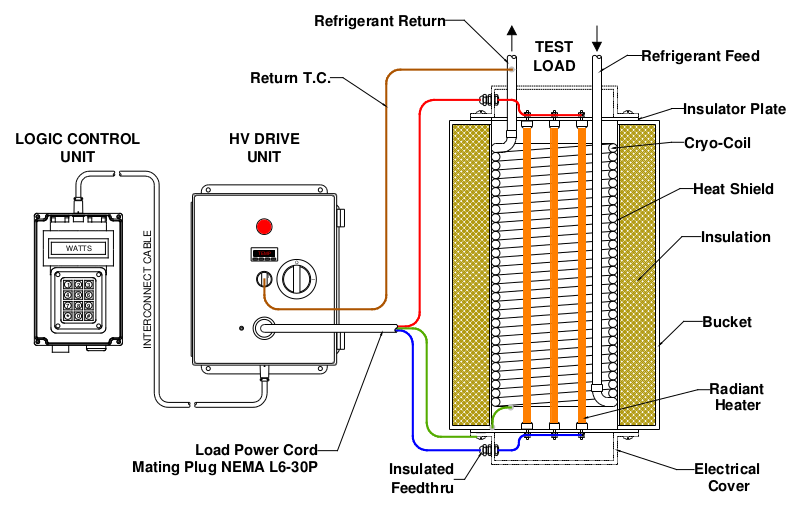
Early 2006 Mytek Controls Heat Load Controller as used in Typical Application
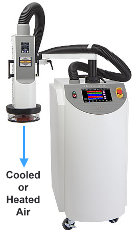 MPI Thermal TA-5000
 Now I'll fast forward to the present day, where I'm approaching my 9th year of being in business with a Taiwan based company called MPI Thermal who's primary mission is focused on producing environmental and stress testing systems for electronics manufacturers that need to qualify their products to work reliably any place on Earth. So this could be the Flaming Mountain outside of the Taklimakan Desert of China during the Summer (80°C/175°F), or Antarctica in the dead of Winter (-93°C/-130°F).
The current product line of MPI Thermal consists of three different models of gas chillers (or gas heaters depending upon the mode of operation) that flow either chilled or heated compressed air over active electronic devices under test. And in order to verify the unit's capabilities during development and production, a calibrated flow meter is used with a variable compressed air source.
I'm anticipating new chiller designs to come that will require a simulated radiant heat source for testing, being very similar to what I was doing back in 2006. And because this testing apparatus will be for my own use, and confined to my own test lab (strictly non-commercial in nature), I decided to base the controller on one of my Atari motherboard creations. Specifically the 576NUC+. It should be fun.
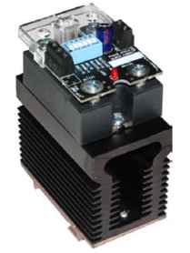 SCR Phase Angle Control Module
 The Project
This all began about 3-4 months ago when I was staring at a completed 576NUC+ board in my hands, and started thinking what a small and powerful package it really was. Size-wise it was very much like those single board computers I remember seeing being advertised in the back pages of electronics magazines in the early 2000's. In fact it was even smaller then many of the ones I recalled from back in the day.
So what would it take to industrialize it for connection to real world devices? It would need some kind of data acquisition expansion board. Something that would allow it to read a wattage transducer and control an SCR based power device to feed power to a heater, and to activate some relays as well as monitor an over temp contact on a temperature module for safety.
Also I needed a way to get a program to load automatically at power-up (SDrive) that would serve as the heat load control software. And there should be a numeric keypad to enter a load set point.
And last but not least I want to mount all of this in a nice rugged 19" rack case to keep it well protected, and to keep the high voltage stuff safely tucked away.
Well first things first... I got right to work on the Data Acquisition expansion board, had great success on accommodating all the requirements, and even added an RS232 communications port. I then sent the board design off to JLCPCB for manufacture, and got the boards in my hands about 5 days later. Assembly took less than a day, and on the following day I assembled a slightly customized 576NUC+ board that would get mated up to my previous days work. Here's what that all looks like...
Enter the RLC-4000 576NUC+ INTFC Carrier Board
| RLC-4000_INTFC_schema.pdf |
Firmware
After assembling the first board set, I needed a way to run some preliminary tests to be sure things would work the way I had in mind. So I divided the tasks between machine code for the DAQ driver, and Altirra Basic for the actual control/monitoring aspect.
FILE: DAQ.SRC
10 ;*********************************
20 ;* *
30 ;* RLC-4000 DAQ Driver *
40 ;* MAX187(ADC) MCP4921(DAC) *
50 ;* DEC 26 2021 *
60 ;* 4000 WATT Heat Load CONTROL *
70 ;* *
80 ;* By: MyTek Controls *
90 ;* *
95 ;*********************************
110 ;
120 DAQMSB=$06F0 ; 12-bit OUT (0-5V)
130 DAQLSB=$06F1
140 ADCMSB=$06F2 ; 12-bit IN (0-5V)
150 ADCLSB=$06F3
160 PORT=$D300 ; PIA PORTA
170 SDO=$D010 ; SPI-SDO (TRIG0)
180 SCK=1 ; SPI-SCK PORTA.0
190 SDI=2 ; SPI-SDI PORTA.1
200 CS1=4 ; ADC-CS PORTA.2
210 CS2=8 ; DAC-CS PORTA.3
220 ;
230 *=$0600
240 ;
250 ;=== READ MAX187 X=USR(1536) ===
260 ;
270 PLA ; BASIC ENTRY POINT
280 LDA #CS1
290 EOR #$FF
300 AND PORT
310 STA PORT ; ADC-ON CS1 LOW
320 LDA #0
330 STA ADCMSB ; zero storage
340 STA ADCLSB ; registers
350 WAIT LDA SDO
360 CMP #1 ; End Of Conversion?
370 BNE WAIT ; not yet...
380 JSR ADCREAD ; retrieve ADC value
390 LDA #CS1
400 ORA PORT
410 STA PORT ; ADC-OFF CS1 HIGH
420 RTS
430 ;
440 ADCREAD LDX #4
450 JSR CLKHI
460 JSR CLKLO
470 RLOOP JSR CLKHI ; read High-Byte
480 LDA ADCMSB
490 ASL A
500 ORA SDO
510 STA ADCMSB
520 JSR CLKLO
530 DEX
540 BNE RLOOP
550 LDX #8
560 RLOOP2 JSR CLKHI ; read low-Byte
570 LDA ADCLSB
580 ASL A
590 ORA SDO
600 STA ADCLSB
610 JSR CLKLO
620 DEX
630 BNE RLOOP2
640 RTS ; read all 12-bits
650 ;
660 ;=== WRITE MCP4921 X=USR(1623) ===
670 ;
680 PLA ; BASIC ENTRY POINT
690 LDA #CS2
700 EOR #$FF
710 AND PORT
720 STA PORT ; DAC-ON CS2 LOW
730 LDY DAQMSB
740 JSR DAQSEND ; write DAC MSB
750 LDY DAQLSB
760 JSR DAQSEND ; write DAC LSB
770 LDA #CS2
780 ORA PORT
790 STA PORT ; DAC-OFF CS2 HIGH
800 RTS
810 ;
820 DAQSEND LDX #8
830 LOOP TYA
840 CLC
850 ASL A
860 BCC ZERO
870 TAY
880 LDA #SDI
890 ORA PORT
900 STA PORT
910 JMP CLKIT
920 ZERO TAY
930 LDA #SDI
940 EOR #$FF
950 AND PORT
960 STA PORT
970 CLKIT JSR CLKHI
980 JSR CLKLO
990 DEX
1000 BNE LOOP
1010 RTS
1020 ;
1025 ;========= SPI CLOCK SR =========
1030 ;
1040 CLKHI LDA #SCK
1050 ORA PORT
1060 STA PORT ; SCK HIGH
1070 RTS
1080 CLKLO LDA #SCK
1090 EOR #$FF
1100 AND PORT
1110 STA PORT ; SCK LOW
1120 RTS
1130 .END
FILE: HEATLOAD.BAS
10 DAQMSB=1776
20 DAQLSB=1777
30 ADCMSB=1778
40 ADCLSB=1779
50 CONFIG=48
60 REM PIA SET-UP
70 POKE 54018,56:POKE 54016,255:POKE 54018,60:POKE 54016,28
80 REM
90 REM ======== MAIN PROGRAM ========
95 REM
100 INPUT N:IF N>3439 THEN ? "ý":GOTO 100
120 POKE DAQMSB,INT(N/256)!CONFIG
130 POKE DAQLSB,N&255
140 X=USR(1623):REM WRITE TO DAQ
150 FOR X=1 to 200:NEXT X:REM PAUSE
160 X=USR(1536):REM READ ADC VALUE
170 ? (PEEK(ADCMSB)*256)+PEEK(ADCLSB)
180 GOTO 100
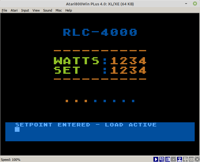
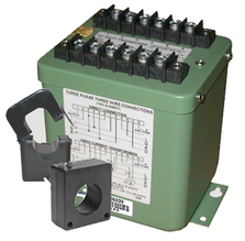 Watt Transducer
 What does RLC-4000 stand for?
Rack Load Controller - 4000 watts max.
Heat Load Control Algorithm
Using Altirra Basic for the control program has some definite advantages over using the stock Atari Basic when it comes to the expanded bit manipulation capabilities of Altirra (!=OR %=EOR &=AND). Also better code structure will be possible by utilizing the enhanced IF, THEN, ELSE, ENDIF features. And of course writing the main control algorithm in interpreted Basic allows for quick changes on the fly when perfecting the closed-loop control.
The basic idea (excuse the pun) is to have the ADC connected to a watt transducer that monitors the voltage and current (amps) going into the heater, and automatically converts that into a digital representation of voltage (0-4.095V) that represents the wattage (1mv/per watt). Since the ADC's 12-bit output directly equates to milivolts (1mv = 1 = 1 watt, 4095mv = 4095 = 4095 watts), no conversion necessary.
The DAC's 0-5V output will be controlling a Phase Angle SCR module to feed power to the heater, which is proportionally based on the control voltage coming from the DAC.
The Control Program will form a closed loop between these two aspects, and precisely maintain a wattage based on the set point that was entered, by constantly controlling the DAC's output, and thus the actual power feeding the heater, while monitoring the ADC so as to not overshoot or undershoot the target.
Since there will be a 7" color LCD screen built into the design, I plan to take advantage of the Atari graphical abilities and have some interesting, as well as useful information being displayed. It should look quite nice, only limited by my programming abilities.
Possible Layout for LCD Screen
Well that pretty well covers it for now - stay tuned for more to come as this project takes form over the next few months.
- Michael
- Michael
 RSS Feed
