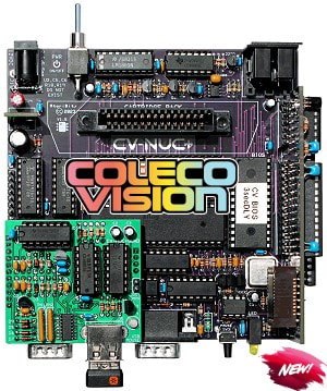
The design has finally been completed after about 9 months of some very challenging development work. And as of one week ago the final pieces needed to manufacture this system got released to Marlin over at The Brewing Academy, with him and I launching our CV-NUC+ webpages on the same day.
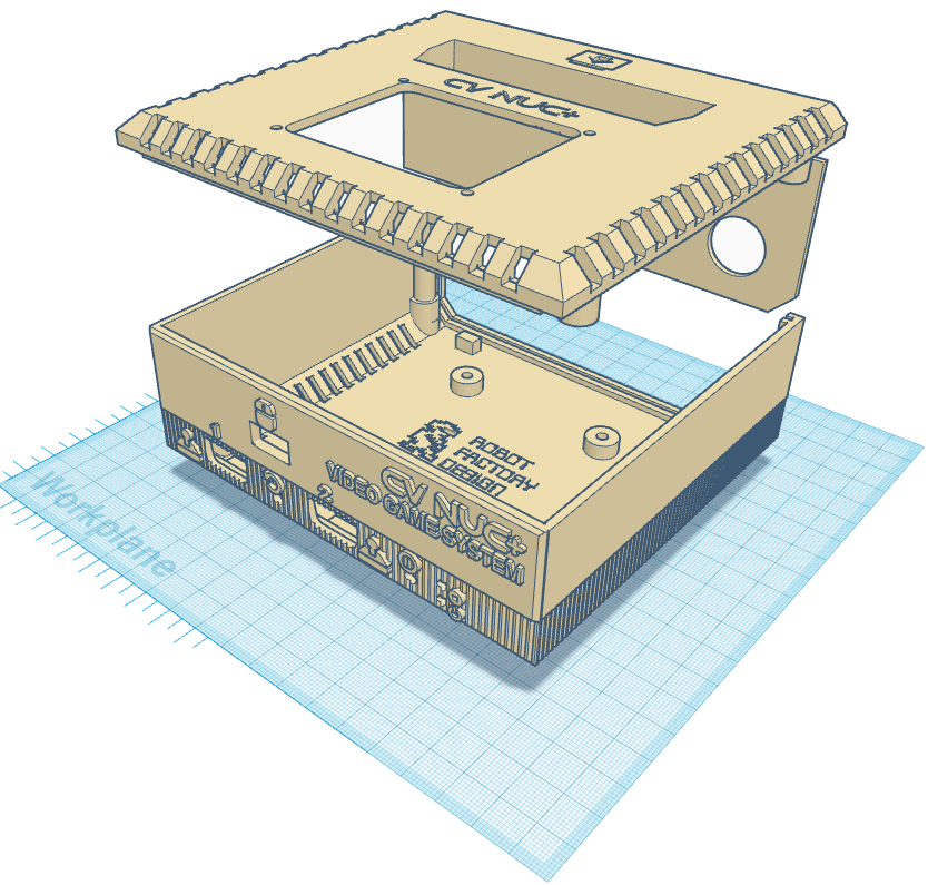
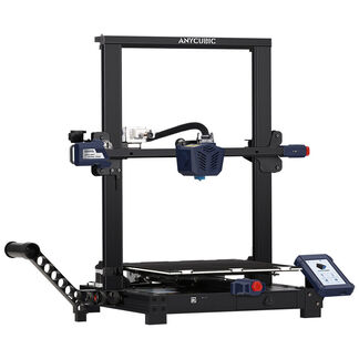
During the development phase of this project I learned a lot about CPLD programming, 3D printing. And also the technical as well as historical aspects of the ColecoVision Game Console and Coleco the company during this pursuit.
Things like Coleco starting out as a leather goods company, then switching to portable swimming pools, and then game systems with some early handheld and pong variants was all new info to me.
Later I learned about the aggressive R&D that went into the creation of the ColecoVision and Adam Computer Systems. And of course all the future products that were being dreamed of, but never came to pass, much of it the result of the 1983 North America Game Crash. Shades of Atari.
So are we Really Done?
Yeah it's kinda bittersweet, but this marks the end of the development aspect for me at least. In many ways that's good. The people that have anxiously been waiting for this, will now have the chance to own one either through building it themselves or buying a pre-assembled one from TBA. For me the excitement that comes through creation has now begun to rapidly fade into the distance. But it's all good.
There will still be a few things I will explore, such as having a resin printed case made at some point to see what that would look like. And who knows I might dream up an upgrade or two for this new little game system, but don't hold your breathe on that one because my mind is presently blank as to what that could possibly be.
Stay Tuned for more Assembly Tips and Tricks...
I'm sure as time goes on and the DIY people try their hand at putting one of these together there will inevidently be questions that'll come up. Some of those will get answered in the AtariAge forums, some might get talked about in the assembly manual in the download section, and some topics might get their own blog posts, so check back here from time to time.
That's it for now -- Enjoy!!!
- Michael


 RSS Feed
