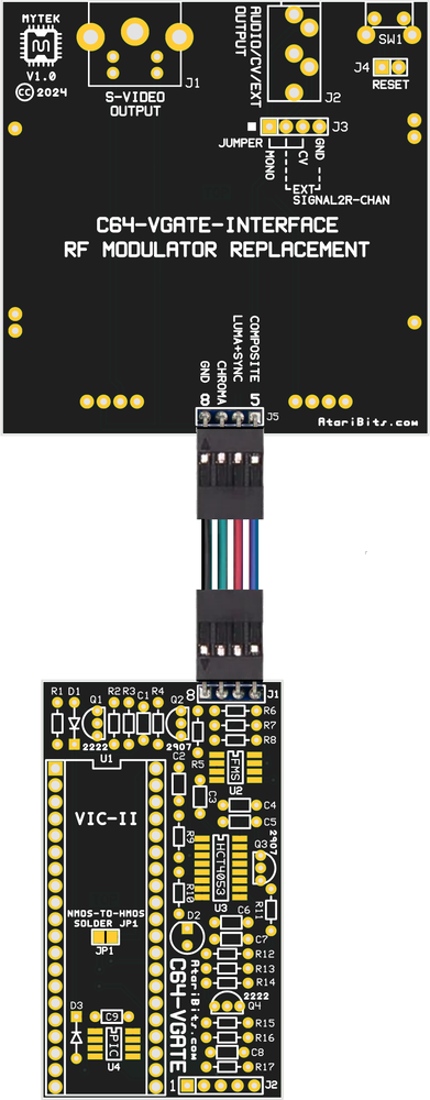
The top board as the silkscreen describes is meant to replace the stock RF Modulator utilizing a few of the existing mounting holes to line up the board with its S-Video and Audio jacks to the holes in the rear of the case. This is then interconnected with the C64-VGATE Main board via a short dual female Dupont Cable (I tried to make this a straight shot to keep the cable flat and untwisted).
The 3.5mm Stereo jack outputs the stock SID audio to the left channel, with provision to route either a 2nd SID audio to the right channel, or gives the option of having Composite or perhaps LumaCode video on this output instead. I got the idea to do this multi purpose assignment by watching a similar project on TheRetroChannel.
The C64-VGATE Main board contains the meat of this project, containing all of the actual electronics that perform the signal amplification, conditioning, and over-scan elimination of the video from the VIC-II chip which it piggybacks. The RF Replacement board is passive, containing only headers and jacks.
There is also provision for installing a later HMOS version of the VIC-II chip in the older NMOS boards, thus eliminating the necessity of an adapter board.
And finally if one is inclined to do so, a small hole can be drilled in the back of the case next to where the 3.5mm jack resides for an optional hard reset switch. I also glommed onto this idea from The RetroChannel's project, and although it got eliminated on their 2nd revision board, I decided it was a good idea to incorporate this idea into my board for that just in case scenario.
Schematics
| Changes: R1 individual values for NMOS or HMOS VIC-II variants, | ||
On March 4th erratic operation was observed in the smoothing capacitor circuit caused by PNP transistor Q3's collector being in a floating state when not turned ON, thus requiring a pull-down resistor for its OFF state. The pull-down resistor reused the component ID "R11" due to its location on the board, and all others that followed had their IDs incremented by one. This can't be seen in the board image above, but was reflected in the schematics.
Also after receiving an eBay Canada C64C which had the short motherboard (PCB ASSY: 250469), I was able to take measurements and create a new short board version of the RF Replacement Interface PCB, and then add it to the documentation, as well as generate gerber files for future release.

 RSS Feed
